Case Study: A Preliminary Step in Aerodynamic Force Modeling for RecurDyn Simulations
Introduction
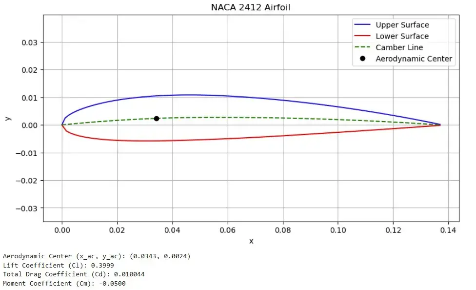
This case study demonstrates the integration of a custom aerodynamic force calculation into RecurDyn using a simplified fluid model for a NACA airfoil profile. This step provides a foundation for accurately simulating lift and drag forces in multibody systems, enabling engineers to analyze dynamic systems under real-world conditions. While this implementation uses a simplified approach, the derived aerodynamic forces and kinematic data can also be processed further for advanced fluid solvers, making it a versatile and scalable solution.
By bridging basic aerodynamic modeling with multibody dynamics, this approach not only enhances simulation precision but also serves as a preparatory step for coupling RecurDyn with specialized fluid dynamics tools.
Simplified Aerodynamic Modeling: Laying the Groundwork
This simplified fluid model enables the extraction of crucial multibody simulation (MBS) data, such as local velocity components and aerodynamic forces, within RecurDyn. These outputs not only provide valuable insights for early-stage system analysis but also establish a basis for advanced fluid solver integration.
The streamlined calculations ensure efficient real-time simulation while maintaining sufficient accuracy for downstream fluid dynamics processing. This adaptability makes it possible to incorporate specialized solvers in future iterations, bridging the gap between simplified modeling and high-fidelity computational fluid dynamics (CFD).

Methodology and Aerodynamic Force Formulas
To calculate the aerodynamic lift and drag forces acting on a NACA airfoil, a systematic methodology is employed. This involves transforming the global velocity components into the airfoil’s local coordinate system, determining the angle of attack, and applying simplified fluid dynamics principles to compute the lift and drag coefficients. These coefficients are then used to derive the corresponding forces.
Step 1: Transforming Global Velocity into Local Coordinates
The airfoil’s motion is described by its yaw (ψ), pitch (θ), and roll (φ) angles, which are used to create a rotation matrix (A). This matrix transforms global velocity components (Vg,x, Vg,y, Vg,z) into the local coordinate system:
Vl = AT ⋅ Vg
Here:
- AT is the transpose of the rotation matrix A.
- Vg is the global velocity vector, and Vl is the resulting local velocity vector.
Step 2: Calculating the Angle of Attack (α)
The angle of attack is a critical parameter for determining the aerodynamic forces. It is calculated from the local velocity components as:
α = arctan(Vl,x / Vl,z) − π / 2
This equation considers the inclination of the airfoil relative to the incoming airflow.
Step 3: Computing Lift and Drag Coefficients
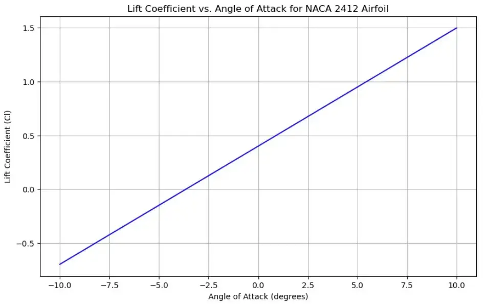
For small angles of attack, the lift coefficient (Cl) is approximated using a linear relationship:
Cl = 2π α
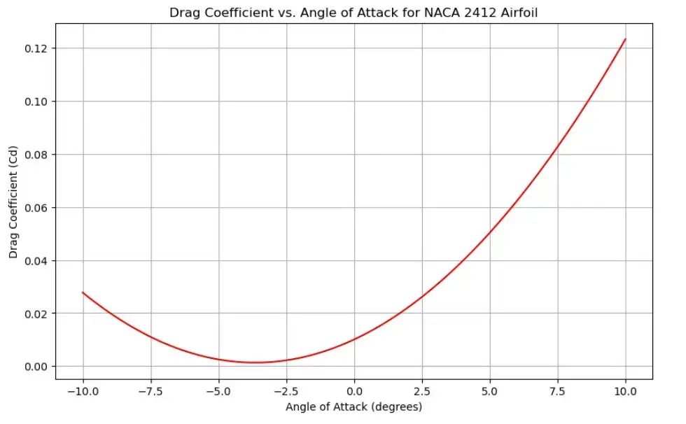
The drag coefficient (Cd) is derived from the skin friction drag formula:
Cd = 1.328 / √Re
where Re is the Reynolds number, representing the flow regime.


Step 4: Calculating Aerodynamic Forces
Using the coefficients and the local velocity magnitude (v):
v = √(Vl,x2 + Vl,z2)
The lift (Flift) and drag (Fdrag) forces are calculated as:
Flift = Cl ⋅ 0.5 ⋅ ρ ⋅ v2 ⋅ c ⋅ b
Fdrag = −Cd ⋅ 0.5 ⋅ ρ ⋅ v2 ⋅ c ⋅ b
Here:
- ρ is the air density.
- c is the chord length.
- b is the wing span.
Step 5: Returning Forces to the Global Frame
The lift and drag forces, initially calculated in the local frame, are transformed back to the global frame for integration with RecurDyn’s solver:
Fg = A ⋅ Fl
This ensures compatibility with the multibody simulation environment.
Results and Practical Applications
These results provide engineers with actionable insights into system behavior and open pathways for integrating advanced computational fluid dynamics (CFD) models.
Key Results
-
Fast Force Calculation
The subroutine successfully computes lift and drag forces dynamically during RecurDyn simulations. -
Enhanced Multibody Dynamics Analysis
By incorporating aerodynamic forces directly into RecurDyn's multibody solver, engineers can analyze systems where structural and aerodynamic interactions play a critical role, such as:- Aircraft wings during flight maneuvers.
- Wind turbine blades under varying wind conditions.
- Automotive components exposed to aerodynamic loads.
-
Accuracy of the Simplified Model
Despite its computational simplicity, the model provides reasonable accuracy for small angles of attack and low Reynolds numbers. This makes it an ideal tool for:- Early-stage design and feasibility studies.
- Iterative optimization processes where rapid feedback is critical.
Practical Applications
-
Early-Stage System Design
Engineers can use this simplified model to perform rapid simulations and identify potential design improvements before involving more resource-intensive CFD simulations. -
Preprocessing for CFD Models
The subroutine’s output, including local velocity components, angles of attack, and force vectors, can be directly used as boundary conditions or input data for high-fidelity CFD tools. This hybrid approach balances computational efficiency with the need for precision. -
Multidisciplinary System Analysis
The integration of aerodynamic forces into RecurDyn enables simultaneous analysis of structural dynamics, control systems, and aerodynamics, leading to a more holistic understanding of system performance.